|
|
||||||||||||||||||||||||||||||
|
Abstract
Utilizing a thermal imager and specialized software can complete this process in a matter of a few seconds and almost all possible failure modes can be detected and recorded for future quality records. A thermal image of the defective grid will aid in the process of repairing the grid.
This process cuts the time for testing, eliminates costly fixtures and improves the determination of any failures. This improves or cuts the failure rate in the field and the replacement cost to the manufacturer.
Introduction
The present methods of detecting these failures are mostly mechanical. One method is to have two aluminum rollers roll over the grids. The rolls check the electrical continuity of the grids and the software counts the number of grid lines detected. This process has the problem of keeping the wheels clean to insure proper electrical contact and the process usually will not find hot spots because there is electrical continuity on grids with hot spots.
The second method is to have an electrical sensor that can detect electrical current present in a grid. This sensor is passed over the grids and as each grid is sensed the processor counts the grids to insure all of them are working. The process requires careful adjustment of the sensor and does not find the hot spots. The third method is a metal wheel with a thermocouple imbedded in the wheel. The thermocouple measures the temperature of the grid and determines the number of grids that are hot. Again keeping the wheel clean and in contact with the grid is difficult. The process is slow requiring times of 25 to 30 seconds and if there are several zones each zone has to be checked.
All of these processes have several problems. They are slow, often requiring up to 25 to 30 seconds to complete the process. The equipment is difficult to keep clean and running properly. The process often requires expensive mechanical stations, with robots to do the testing. The glass has to come into the test stand at basically the same temperature all of the time so that the (T detected indicates the grid temperature not a change in window temperature. The sensors do not tell the operator where the grid has failed. The operator has to visually look for the broken grid. In most cases the sensors do not find the hot spots because the grid is working at the time of the test but after many uses in the field the grid will fail requiring a costly replacement.
The window producer has two major problems. Their system fails to find defects and passes them onto the automobile producer and the system often fails good windows causing a high scrap rate for the supplier.
Solution
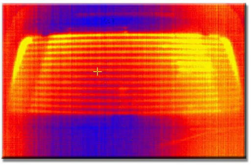
What is a thermal imager? It is a non-contact infrared thermometer that uses a special detector called a Focal Plan Array (FPA) This detector is a flat plane detector with 76,800 individual detectors called pixels. These pixels are arranged in an array of 320 x 240 individual points. This detector can look at the rear light and provide a complete thermal picture of the product in 1/30 of a second. This thermal picture instantly shows the operator where both the broken grids and hot spots are on the glass.
The real time and money saver is the special software program that is incorporated into the imager and can make the process totally automated. This software provides the following features.
1. The glass need not be perfectly aligned in the testing station. Location errors of 1 ì (25mm) are allowed. This makes the mechanical station less expensive to build and maintain. The process may eliminate the use of costly robots.
2. The thermal imager looks at the glass as soon as it enters the test stand and takes an image. This gives the software program a complete temperature image of the glass before the grid is heated. This means the glass can come into the test stand at any temperature, even with temperature gradients and the software will measured the entire window.
3. The grid is now heated with usually a 24-volt supply. The higher the voltage the faster the test and more accurate the response. Within two seconds after the grid is heated the software again takes the entire image of the glass and subtracts out the original image leaving only the hot grid pattern on the screen. (This can take less than 2 seconds to complete)
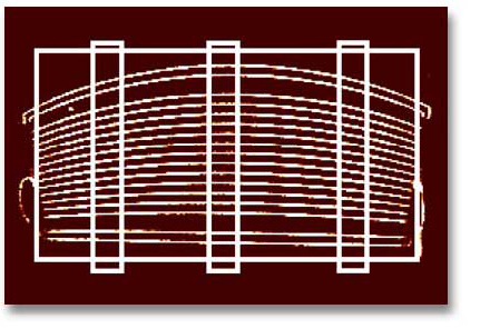
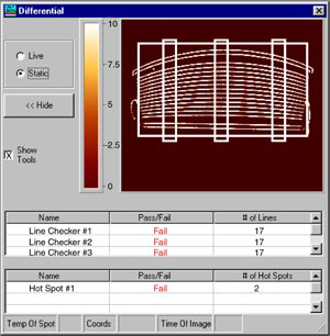
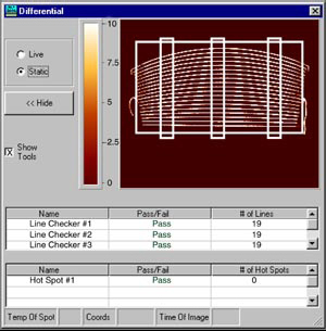
4. The software has the capability of drawing a LINE ROI (Regions of Interest.) If the grid is divided into 2, 4, 6 or 8 zones you will draw the same number of LINE Rioís, one line for each grid zone.
Along the ROI line the software will count the number of lines above a threshold temperature thus indicating the number of working grids. The software is set up to count a specific number of grid lines and if one or more grids are not working the count will be less than the desired amount and an alarm will ring. In addition an image will be saved which can be called up to show the operator where the part failed and it can then be quickly be repaired.
5. In addition to the broken grids the software will have one ROI, in the form of a rectangle that covers the entire window. Any spot that is really hot or several degrees above the glass temperature are an indication of a hot spot. Again an alarm will ring and the image saved to allow the defect to be fixed.
_
6. The software saves the entire setup for each type of glass and grid pattern and can be saved by a part number. When the same part number is reintroduced in a matter of seconds the setup can be installed in the software and the process is ready for operation.
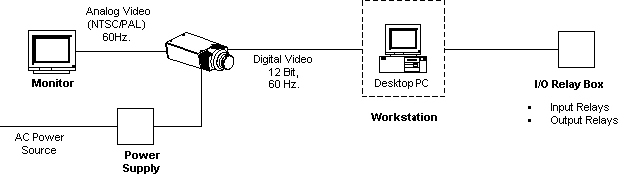
7. The entire process of taking images, testing and saving can all be controlled with a PC, thus making the operation entirely automatic. In addition relay contacts can be supplied for the alarms. Conclusion
The combination of the thermal imager and the software provide the following advantages:
|
|
||||||||||||||||||||||||||||
|
||||||||||||||||||||||||||||||